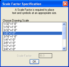
Example DUCTWORK Usage
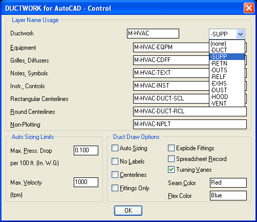
Next, the DUCTWORK Control Dialog Box allows you to specify layers to be used by the system. You can use this to draw supply ductwork on different layers from return ductwork, etc. As you draw ductwork, you never have to concern yourself with what your 'current' layer is, ductwork and all other items are automatically placed on the correct layer.
You can also specify the Duct Modes from this dialog box: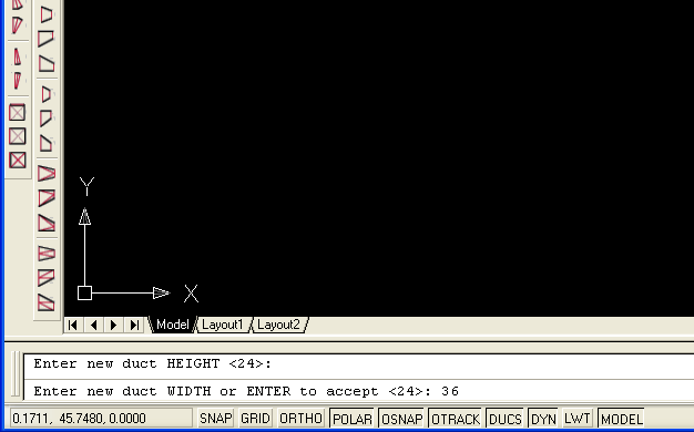
Place a new Duct Cursor where you want the duct to start. The program prompts you for duct size and starting directions. Type 'NDC' to place a New Duct Cursor.
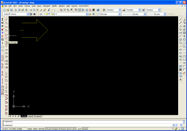
The Duct Cursor is placed. Choose your fitting from the toolbar...
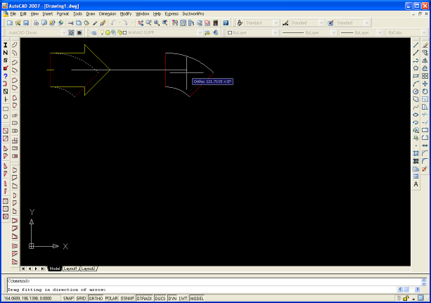
The fitting is placed initially at the location of the Duct Cursor. Then you drag the fitting into place. As you drag, the new fitting is locked othogonally in alignment with the duct cursor. You can also type the distance if you want. Then...
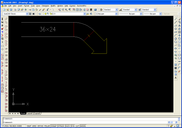
The fitting is re-draw in its final position, and the Duct Cursor is advanced to the outlet of the new fitting.
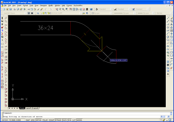
The process is repeated...
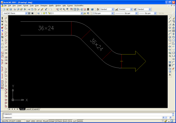
until the entire duct system is drawn.